TM-9-2330-356-14
SEMITRAILER, TANK: 5000 GALLON, BULK HAUL, SELF LOAD/UNLOAD M967 AND M967A1; SEMITRAILER, TANK: 5000 GALLON, FUEL DISPENSING, AUTOMOTIVE M969 AND M969A1; SEMITRAILER, TANK: 5000 GALLON, FUEL DISPENSING, UNDER/OVERWING AIRCRAFT M970 AND M970A1
TECHNICAL MANUAL; OPERATOR’S, UNIT, DIRECT SUPPORT, AND GENERAL SUPPORT MAINTENANCE MANUAL
OCTOBER 1990
TM-9-2330-356-14 - Page 201 of 528
TM 9-2330-356-14
c.
Replacement of Preheat indicator Light.
Refer to
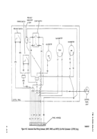
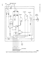
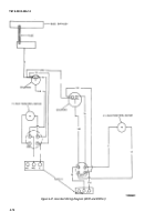
figures 4-39 and 4-41, and engine control panel schematic
figures 4-42 and 4-43 as guides for replacement of
indicator light.
(1)
Removal.
(a)
Disconnect negative battery lead from
battery (para 4-23).
(b)
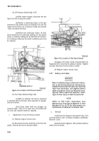
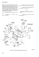
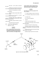
Remove six screws (fig. 4-39) securing
control panel door and pull door open. Hold door ata90°
angle with control panel with a 20-inch length of safety
wire threaded through one hole in door and
corresponding hole in control panel.
(c) Separate indicator light socket
(fig. 4-39) from light body by pulling on socket.
(d)
Remove nut and washer securing light
body to control panel door. Remove light body.
(e)
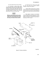
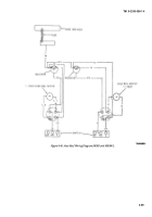
Remove crimp splices (fig. 4-41) on the
indicator light ground leads. Disconnect the other lead
from control panel harness.
(f)
Remove indicator light socket.
(2)
Installation.
(a)
Insert light body (fig. 4-39) through hole
in door and secure with washer and nut.
(b)
Insert socket into light body.
(c)
Connect the light ground lead (fig. 4-41)
to the existing wire using a crimp splice. Install remaining
wire by crimping splice to control panel harness.
(d)
Remove safety wire from control panel
door and close door. Be sure that tubing to gages is not
folded or crimped. Secure door with six screws.
(e)
Install battery negative ground lead
(para 4-23).
d.
Preheat Indicator Light Lamp Replacement.
(1) Remove six screws (fig. 4-39) securing
control panel door and pull door open.
(2) Separate indicator light socket from light
body.
(3) Remove lamp from the indicator socket and
install a new lamp.
(4) Replace indicator light socket into light body.
(5) Close panel door. Be sure that tubing to gages
is not folded or crimped. Secure door with six screws.
e.
Replacement of Control Panel Plate.
Remove all
switches, gages and light following instructions in
b
and
c
above. Remove four capscrews (fig. 4-39) which fasten
plate to control panel. Remove control panel plate. Install
new plate and reinstall switches, gages, and light.
f.
Repair of Wiring.
Repair any cracked, cut, or
broken insulation with electrical tape (item 29, Appendix
E). Replace wiring when damage cannot be repaired.
Tighten loose connections.
4-25. Control Panel Wiring Harness and Conduit
WARNING
When troubleshooting an electrical malfunc-
tion or performing electrical maintenance,
ALWAYS disconnect intervehicular electrical
cable from semitrailer, and negative battery
cables at batteries. Failure to follow this warn-
ing may create a spark and explosion, result-
ing In serious injury or death to personnel.
a.
Repair of Wiring.
Repair any cracked, cut, or
broken insulation with electrical tape (item 29, Appendix
E). Replace wiring harness when damage cannot
repaired.
b.
Replacement of Control Panel Wiring Harness.
(1)
Removal.
(a)
Open control panel by removing
be
six
round head screws (fig. 4-39) and swinging panel down.
(b)
Disconnect all electrical leads and
jumper assemblies from control panel wiring harness
(fig. 4-41).
(c)
With a wire cutter, remove all terminals
from the ends of the harness wires.
(d)
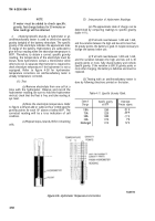
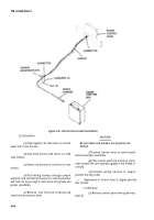
Disconnect the wiring harness from the
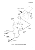
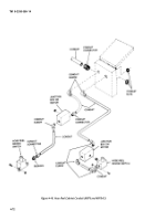
engine junction box (fig. 4-44).
(e)
Secure a strong cord, about ten feet
longer than the harness, to the end of the wiring harness.
(f)
Pull harness out of conduit and allow
cord to be pulled into the conduit. When harness is out,
cord should be visible at both ends of conduit.
4-65
Back to Top

