TM-9-2350-238-20-1 - Page 793 of 1364
TM 9-2350-238-20-1
1
2
3
4
5
6
7
8
9
10
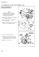
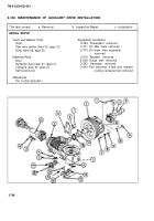
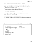
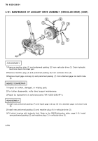
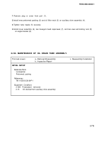
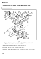
Disconnect electrical connector (1) from auxiliary drive assembly (2).
Tag and disconnect four electrical leads (3).
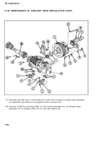
Remove four hexagon plain nuts (4), two flat washers (5), and two shoulder screws (6).
Remove Iockwire (7), two hexagon head capscrews (8), and angle bracket (9).
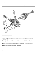
Remove Iockwire (10) and four hexagon head capscrews (11). Disconnect power takeoff drive
shaft (12) from auxiliary drive assembly (2).
Remove Iockwire (13) and four hexagon head capscrews (14). Disconnect magnetic clutch to
bearing unit drive shaft (15) from auxiliary drive assembly (2).
Remove self-locking nut (16), hexagon head capscrew (17), two sleeve spacers (18), and
rubber grommet (19) from connecting link (20).
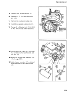
Attach sling and carefully remove auxiliary drive assembly (2) and attached parts from hull
using hoist.
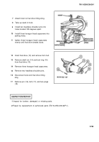
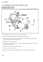
If damaged, remove Iockwire (21), six hexagon plain nuts (22), six hexagon head capscrews
(23), two mounting brackets (24), and two mounting plates (25).
Loosen screw and remove flat hose clamp (26). If damaged, remove boot (27).
1
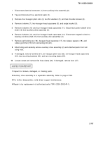
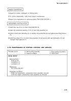
Inspect for broken, damaged, or missing parts.
2
Auxiliary drive assembly is a repairable assembly. Refer to page 2-769.
3
For further disassembly, notify direct support maintenance.
4
Repair is by replacement of authorized parts (TM 9-2350-238-24P-1).
2-767
Back to Top

