TM-9-2350-238-20-2 - Page 173 of 495
TM 9-2350-238-20- 2
INSTALLATION
1
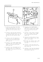
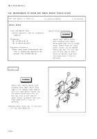
If necessary, install boom winch brak e
pressure identification plate (1) on ca b
assembly winch controls access cover (2 )
and secure with two new drive screw s
(3) .
2
If necessary, install tow winch brake pres -
sure selector identification plate (4) on ca b
assembly winch controls access cover (2 )
and secure with two new drive screw s
(5) .
3
If necessary, install filter bypassing in -
struction plate (6) on camlock control s
support (7) and secure with two ne w
drive screws (8) .
4
If necessary, install BOOM LOWER RAIS E
identification plate (9) on camlock control s
support (7) and secure with two ne w
drive screws (10) .
5
If necessary, install TOW WINCH OUT I N
identification plate (11) on camlock con -
trols support (7) and secure with two ne w
drive screws (12) .
6
If necessary, install BOOM WINC H
LOWER-RAISE instruction identificatio n
plate (13) on camlock controls suppor t
(7) and secure with two new driv e
screws (14) .
7
If necessary, install LO-N-HI instructio n
plate (15) on camlock controls suppor t
(7) and secure with two new driv e
screws (16) .
8
If high noise instruction plate (17) wa s
removed, clean mounting surface wher e
plate is to be installed .
9
Apply epoxy resin adhesive (item 2, app x
C) to high noise instruction plate (17)
and install .
10
If necessary, install winch load instruc -
tion plate (18) and secure with four ne w
drive screws (19) .
11
If necessary, install load rating capacitie s
identification plate (20) and secure wit h
four new drive screws (21) .
2-13 3
Back to Top


