TM-9-2350-238-34-1 - Page 117 of 292
CAUTION
TM 9-2350-238-34-1
19
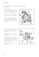
Unsolder electrical leads (39) fro m
receptacle connector contact pins, an d
remove receptacle connector (13) .
INSPECTION/REPAI R
1
Inspect for broken, damaged, or missin g
parts ,
2
Inspect annular ball bearings. Refer to TM 9-
214 .
3
Inspect magnetic clutch for wear or warpag e
of clutch plates and signs of arcing or over-
heating. Spin rotor by hand and listen for
grinding noise. Apply 24 V dc to magnetic
coil and check clutch operation. If damaged ,
refer to general maintenance, page 2-28 .
4
Repair is by replacement of authorized parts
(TM 9-2350-238-24P-1) which do not mee t
inspection criteria .
REASSEMBLY
1
2
3
4
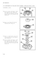
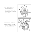
Pack annular ball bearing (1) with grease.
Install clutch bearing shield (2) and annular
ball bearing into mechanical clutch housin g
(3), using clutch bearing replacer
Install retaining ring (4).
and press .
An improperly installed plain encase d
seal will leak during operation.
Lightly lubricate mechanical clutch housin g
seal cavity with grease. Install new plain
encased seal (5), using seal remover an d
replacer. Ensure lip of seal is toward inside
of housing .
Install retaining plate (6) and secure with six
machine screws (7). Stake each machin e
screw in place.
2-10 5
Back to Top


