TM-9-2350-238-34-1 - Page 111 of 292
caution
TM 9-2350-238-34-1
11
Clean any remaining oil from output gear
teeth and apply grease or white ename l
on four or five teeth. Use input shaft
opening in input drive for access.
12
Turn shaft counterclockwise and rotat e
output gears at least one complet e
revolution .
13
Remove three jacking screws and clutc h
drive (9).
14
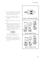
Examine output gear matching gear teet h
and determine gear tooth wear pattern. I f
backlash is correct (fig. 2-1), the gear
tooth bearing contact area shall be equal
in length and centered on tooth face within
10 percent of length and width. The
contact area should be 0.3 to 0.7 in. (7.6
to 17.8 mm).
Contact areas extending to either end
of the teeth are not acceptable.
15
Repeat steps 5 thru 13 if wear pattern is
not correct (fig. 2-2 and 2-3). If wear
pattern cannot be reached through proper
shimming, repair generator drive ( p
2-116) .
2-9 9
Back to Top

