TM-9-2350-238-34-1 - Page 119 of 292
TM 9-2350-238-34-1
1 1
1 2
1 3
1 4
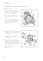
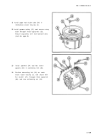
Solder electrical leads (19) to receptacle
connector (20) contact pins. Refer to TB
SIG-222 .
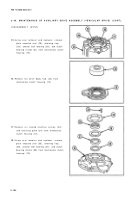
Install bottom part of magnetic clutch (17)
into mechanical clutch housing (3) .
Ensure that lip of inner seal is worked up
and over edge of magnetic clutch (17) and
points inward evenly around clutch .
Place ring spacer (21) in bottom part of
magnetic clutch (17) with external chamfer
down .
Position top part of magnetic clutch (22)
directly over mechanical clutch housin g
(3). Carefully lower magnetic clutch (22)
into mechanical clutch housing (3) ,
rotating slightly to aid the alignment of
magnetic clutch teeth with magnetic clutc h
plate grooves .
2-10 7
Back to Top


