TM-9-2350-260-20-1-3 - Page 562 of 783
TM 9-2350-260-20-1-3
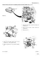
BRAKE PEDAL AND ROD ASSEMBLIES REPAIR AND REPLACEMENT (Sheet 8 of 8)
9.
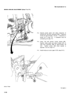
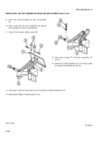
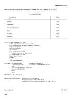
Aline hole in lever assembly (G) with rod assembly
(B).
10. Install screw (M) and new lockwasher (N) through
lever assembly (G) and rod assembly (B).
11. Using 3/4 inch wrench, tighten screw (M).
12. Aline holes in pedal (P) with lever assemblies (G)
and (H).
13. Install two straight headed pins (Q) through pedal
(P) and lever assemblies (G) and (H).
14. Using pliers, install two new cotter pins (R) through two straight headed pins (Q).
15. Adjust brake linkage if required (page 13-10).
End of Task
TA146322
13-34
Back to Top

