TM-9-2350-261-20-2 - Page 112 of 1008
TM 9-2350-261-20-2
REPLACE AUXILIARY POWER (SLAVE) RECEPTACLE (M577A2 AND
M1068 ONLY) — Continued
0219 00
INSTALLATION
NOTE
Steps 1 - 8 tell you how to install the late model slave receptacles. Steps 9 - 11 tell you how
to install the early model slave receptacles.
NOTE
Perform Step 1 only if receptacle is mounted on an adapter (1).
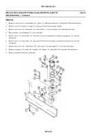
1.
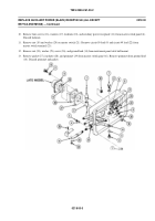
If adapter (1) is used, place new gasket (2) and adapter in hull. Secure with four washers (3), new lockwashers (4), and
screws (5).
2.
Install new bushing (6) in adapter (1) or in hull.
3.
Connect ground lead (7) to negative (
−
) side of post on receptacle (8). Secure with screw (9) and new lockwasher (10).
4.
Place plate insulator (11) and new gasket (12) on adapter (1) or hull.
5.
Insert ground lead (7) into bushing (6) far enough to connect circuit 6 lead (13) to positive (+) side of post on receptacle
(8). Secure with screw (9) and new lockwasher (10).
6.
Secure receptacle (8) with plate insulator (11) and gasket (12) to adapter (1) or hull with four screws (14), new
lockwashers (15), and washers (16).
7.
Inside carrier, install ground lead (7) to hull. Secure with screw (17) and new lockwasher (18) in clamp (19).
8.
Inside carrier, fit ground lead (7) into wiring cradle (20). Secure with clip (21).
0219 00-4
Back to Top


