TM-9-2350-261-20-2 - Page 104 of 1008
TM 9-2350-261-20-2
REPLACE AUXILIARY POWER (SLAVE) RECEPTACLE (ALL EXCEPT
M577A2 AND M1068) — Continued
0218 00
2.
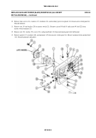
Remove nut (5), circuit 49 lead (6), two washers (7), and screw (8) from terminal on circuit 50 lead (9).
3.
Loosen nut (10) and lockwasher (11) on master switch (12). Remove lead (9) from master switch terminal. Discard
lockwasher.
4.
Remove nut (13), washer (14), screw (15), and ground lead (16) from instrument panel strut hull mount.
5.
Remove four nuts (17), screws (18), receptacle (19), and grommet (20) from panel. Remove grommet from ground lead
(16). Discard grommet.
6.
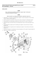
Disconnect circuit 37 lead (1) from connector (2).
7.
Remove eight locknuts (3), washers (4), and screws (5) from master switch panel (6). Pull panel away from distribution
box. Discard locknuts.
8.
Remove screw (7), lockwasher (8), and circuit 50 lead (9) from positive post (10) of auxiliary power receptacle (11).
Discard lockwasher.
9.
Remove screw (12), lockwasher (13), and ground lead (14) from negative post (15) of receptacle (11). Discard
lockwasher.
0218 00-2
Back to Top


