TM-9-2350-261-20-2 - Page 272 of 1008
TM 9-2350-261-20-2
REPLACE DISTRIBUTION BOX ASSEMBLY FOR 200 AMP GENERATOR SYSTEM
(M577A2 AND M1068 ONLY) — Continued
0266 00
2.
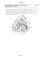
Install new grommet (5) and circuit 2A lead (6) in distribution box (3).
3.
Install new grommet (7) and circuit 2 lead (8) in distribution box (3).
4.
Install new grommet (9) and circuit 400 lead (10) in distribution box (3).
NOTE
If bilge pump circuit breakers were removed, see WP 0327 00 for installation. If bilge pump
circuit breakers were not removed, go to Step 8.
5.
Connect circuit 450A lead (11) to circuit breaker (12).
6.
Connect circuit 450C lead (13) to circuit breaker (14).
7.
Install circuit 450C lead (13) on bus bar (15). Secure with new lockwasher (16) and screw (17).
8.
Install new grommet (18) and circuit 450B lead (19) in distribution box (3). Connect circuit 450B lead to circuit
breaker (20).
9.
Install new grommet (21) and circuit 450 lead (22) in distribution box (3). Connect circuit 450 lead to circuit breaker
(23).
0266 00-4
Back to Top

