TM-9-2350-261-20-2 - Page 339 of 1008
Personnel Required
Unit Mechanic
References
See your -10
Equipment Condition
Engine stopped/shutdown (see your -10)
B attery groun d lead disco nnected (
WP 0294 00
)
Carrier blocked (see your -10)
REMOVAL
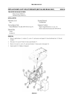
1.
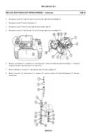
Disconnect circuit 38 lead (1), circuit 38B lead (2), and circuit 38C lead (3) from switch (4).
2.
Remove locknut (5), screw (6), and retainer (7) from actuator (8). Discard locknut.
3.
Remove switch (4) from actuator (8).
4.
Remove two locknuts (9), washers (10), screws (11), and actuator (8) from bracket (12). Discard locknuts.
5.
Remove two locknuts (13), screws (14), and bracket (12) from hull. Discard locknuts.
Removal (page 0283 00-1).
Clean, Inspect, and Repair (page 0283 00-2)
Installation (page 0283 00-2).
Adjustment (page 0283 00-3).
Locknut (4)
Locknut
s
t
r
TM 9-2350-261-20-2
a
P
/
s
l
a
i
r
e
t
a
REPLACE RAMP DOOR SWITCH AND MOUNT (M577A2 AND M1068 ONLY)
0283 00
General Mechanic’s Tool Kit (WP 0780 00, Item 29)
M
s
l
o
o
THIS WORK PACKAGE COVERS:
T
l
a
INITIAL SETUP:
M
i
a
c
i
e
n
p
t
S
e
d
n
n
a
a
nc
s
e
l
o
L
o
e
Unit
T
v l
e
028300-1
WP 0294 00
Back to Top


