TM-9-2350-261-20-2 - Page 775 of 1008
TM 9-2350-261-20-2
REPAIR T150 SPROCKET WHEEL AND TRACK ASSEMBLIES
0384 00
THIS WORK PACKAGE COVERS:
Disassembly (page 0384 00-1).
Assembly (page 0384 00-2).
INITIAL SETUP:
Maintenance Level
Unit
Tools and Special Tools
General Mechanic’s Tool Kit (WP 0780 00, Item 29)
Socket Wrench (WP 0780 00, Item 97)
Torque Wrench (WP 0780 00, Item 103)
Torque Wrench (WP 0780 00, Item 105)
Materials/Parts
Self-locking screws (10)
Self-locking screws (20)
Personnel Required
Unit Mechanic
Helper (H)
DISASSEMBLY
NOTE
Procedures for repairing left and right sprocket wheel assemblies are the same. Make sure you
use matching sprockets. New longer life sprockets are thicker and have a wear indicator on
both sides of the sprocket teeth. Use a set when replacing sprockets on a sprocket wheel.
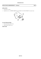
1.
Remove ten self-locking screws (3) and sprocket wheel assembly (2) from final drive (1). Lower sprocket wheel
assembly to the ground. Have helper assist. Discard self-locking screws.
038400-1
Engine stopped (see your -10)
Carrier blocked (see your -10)
Track cover removed (WP 0365 00)
Track broken between sprocket or fifth road wheel (see
your -10)
Track removed from drive sprockets (WP 0367 00)
E
n
q
o
u
i
i
t
p
i
m
d
e
n
n
o
t C
Back to Top


