TM-9-2350-261-20-3 - Page 431 of 932
TM 9-2350-261-20-3
REPLACE LEFT SIDE RACK BASE (M1068 ONLY) — Continued
0532 00
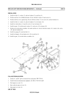
INSTALLATION
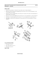
1.
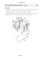
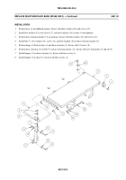
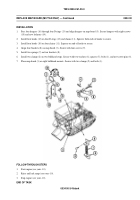
Install two bolts (1), washers (2), and new locknuts (3) in rack base (4).
2.
Position rack base (4) on bulkhead mounts. Secure with three washers (5) and screws (6).
3.
Position rack base (4) to sponson lugs. Secure with four washers (7), two screws (8), and new locknuts (9).
4.
Install two bolts (1), washers (2), and new locknuts (3) in two frames (10).
5.
Install two work surfaces (11) and 12 screws (12) on two frames (10).
6.
Install two pins (13) with lanyards, washers (14), and screws (15) on frames (10).
7.
Position two work surface assemblies (16) under rack base (4). Secure with four washers (17), washers (18), screws
(19), and new locknuts (20).
8.
Install two springs (21) onto four bolts (1).
9.
Install two bumpers (22) and eight screws (23) on rack base (4).
10. Install two pins (13) in work surface assemblies (16).
FOLLOW-THROUGH STEPS
1.
Install A.C. and D.C. power extension boxes and mounts (WP 0735 00).
2.
Install electronic/communication equipment. See TM 11-7010-256-12&P.
3.
Start engine (see your -10).
4.
Raise and lock ramp (see your -10).
5.
Stop engine (see your -10).
END OFTASK
0532 00-3/4 blank
Back to Top

