TM-9-2350-261-34 - Page 321 of 785
TM 9-2350-261-34
REPAIR COMMANDER’S CUPOLA (M113A2, M1059, AND M1064 ONLY) — Continued
0040 00
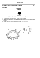
ASSEMBLY
NOTE
If one ball bearing or separator needs to be replaced, all ball bearings and separators must
be replaced.
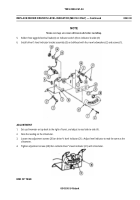
1.
Install inner race (8) on hatch (4).
CAUTION
Improper installation will cause binding, resulting in bearing failure. Bearing block (7) radius
surface must face toward cupola center.
Do not use talcum or other powder to reduce friction. When talcum is exposed to moisture, a
chalky substance will form, causing binding.
NOTE
Alternately, install 24 separators (6) and 23 ball bearings (5) between bearing blocks (7). One
separator (6) is to be installed on each side of each bearing block (7). A maximum number of
sets (one ball and one spacer per set) is needed between any two blocks. The number of sets in
each space between blocks must not differ by more than one set.
2.
Install 140 ball bearings (5), 146 separators (6), and six bearing blocks (7) in groove of inner race (8).
NOTE
The outer race and inner race must be aligned correctly so that the traverse lock pin will fit.
3.
Install outer race (3) on hatch (4). Place large unthreaded hole in outer race (3) directly above largest unthreaded hole in
inner race (8).
4.
Secure outer race (3) to inner race (8) with 18 new lockwashers (2) and socket head screws (1). TIGHTEN SCREWS
TO 25-34 LB-FT (34-46 N·M) TORQUE. Use torque wrench.
FOLLOW-THROUGH STEPS
1.
Install commander’s cupola (WP 0039 00).
END OF TASK
0040 00-2
Back to Top


