TM-9-2350-277-20-3 - Page 77 of 941
TM 9-2350-277-20-3
REPLACE MASTER SWITCH PANEL ASSEMBLY (M577A3 AND M1068A3 ONLY) —
Continued
0261 00
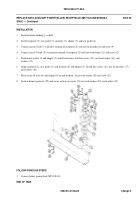
17. Connect wiring harness (24) leads (25) (26)(27) to three circuit breakers (28)(29)(30).
18. If damaged, replace gasket between master switch panel and distribution box (WP 0271 00).
19. Install master switch panel (3) on distribution box (31). Secure with eight screws (32), washers (33), and new
locknuts (34).
FOLLOW-THROUGH STEPS
1.
Connect battery ground lead (WP 0338 00).
2.
Start engine (see your –10). Check that master switch panel assembly is operable.
3.
Stop engine (see your –10).
END OF TASK
0261 00-6
Back to Top


