TM-9-2350-277-20-5 - Page 852 of 1047
TM 9-2350-277-20-5
COMMANDER’S INTERFACE BRACKET ASSEMBLY MAINTENANCE
(MFCS) (M577A3 ONLY) — Continued
0812 02
REPAIR
1.
Replace defective parts as authorized by TM 9-1220-248-23&P and TM 9-2350-277-24P.
INSTALLATION
NOTE
If computer table top mount is being installed in vehicle for the first time, proceed with Step 1.
If computer table top mount is being installed in previously-modified vehicle, proceed to Step 5.
Ensure that cable 4W7 will reach selected position of computer table top mount.
1.
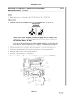
Position cable 4W7 to J3 connector on power distribution assembly (PDA) and selected table top position and verify
that cable will reach position of commander’s interface.
2.
Using top mounting plate (9) as a template, mark locations for three holes (13) on table top (6). Position plate with single
hole facing near edge of table top. Mark single hole position at approximately 20.0 in. (50.8 cm) from right edge of table
and approximately 7.4 in. (18.8 cm) from rear of table.
081202-3
Change 4
Back to Top


