TM-9-2350-311-20-2 - Page 290 of 828
TM 9–2350–311–20–2
5–34
Change 2
5–12 OPERATING CAM — CONTINUED
b.
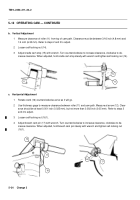
Vertical Adjustment
1
Measure clearance of roller (11) from top of cam path. Clearance must be between 3/16 inch (4.8 mm) and
1/4 inch (6.35 mm). Refer to steps 2 and 3 to adjust.
2
Loosen self-locking nut (14).
3
Adjust cradle cam stop (15) with wrench. Turn counterclockwise to increase clearance, clockwise to de-
crease clearance. When adjusted, hold cradle cam stop steady with wrench and tighten self-locking nut (14).
11
15
14
c.
Horizontal Adjustment
1
Rotate crank (16) counterclockwise as far as it will go.
2
Use thickness gage to measure clearance between roller (11) and cam path. Measure at arrow (12). Clear-
ance should be at least 0.001 inch (0.025 mm), but not more than 0.002 inch (0.05 mm). Refer to steps 3
and 4 to adjust.
3
Loosen self-locking nut (16.1).
4
Adjust breech cam pin (17) with wrench. Turn counterclockwise to increase clearance, clockwise to de-
crease clearance. When adjusted, hold breech cam pin steady with wrench and tighten self-locking nut
(16.1).
16.1
16
11
17
12
Back to Top

