TM-9-2350-311-20-2 - Page 280 of 828
TM 9--2350--311--20--2
5--24
5--9
CARRIER ASSEMBLY — CONTINUED
b. Disassembly — Continued
16
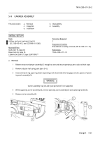
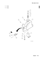
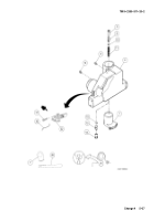
Remove rack plate (38), gear rack (39), and stop (40) that restrains helical compression springs (41 and
42).
WARNING
Stop and detent plunger hold compressed springs. Use care during disassembly to avoid possible
injury.
17
Remove spring pin (43) while restraining detent plunger (44) and helical compression spring (45). Discard
spring pin.
18
Remove detent plunger (44) and helical compression spring (45).
c. Inspection
NOTE
If any of the parts below are unserviceable, replace as required.
1
Inspect springs (41 and 42) for cracks and distortion.
2
Inspect operating crank assembly (3) for visible cracks.
3
Inspect carrier assembly (4) for cracks and distortion.
4
Place machinist’s rule on cut-away end of detent plunger (44) and measure for excess wear. Replace if
detent plunger measures less than 31/32 inch (24.6 mm) at any point.
d. Assembly
WARNING
Detent plunger and stop hold compressed springs. Use care during assembly to avoid possible in-
jury.
1
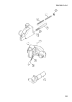
Install helical compression spring (45), detent plunger (44), and new spring pin (43) in carrier assembly (4).
2
Lubricate helical compression springs (41 and 42) with GAA and install in gear rack (39). Install gear rack,
stop (40), and rack plate (38).
Back to Top

