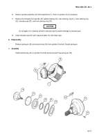
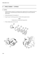
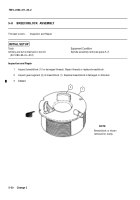
TM-9-2350-311-20-2 - Page 275 of 828
TM 9–2350–311–20–2
5–19
NOTE
•
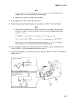
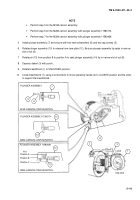
Perform step 5 for the M185 cannon assembly.
•
Perform step 6 for the M284 cannon assembly with plunger assembly 11580174.
•
Perform step 7 for the M284 cannon assembly with plunger assembly 11580469.
5
Install plunger assembly (7) and secure with two new lockwashers (6) and two cap screws (5).
6
Rotate plunger assembly (10) to release from cam plate (12). Be sure plunger assembly tip seats in narrow
slot of nut (8).
7
Rotate pin (13) from position B to position A to seat plunger assembly (14) tip in narrow slot of nut (8).
8
Depress detent (3) with punch.
9
Rotate breechblock (1) to UNLOCKED position.
10
Close breechblock (1), using one mechanic to move operating handle (2) to CLOSED position and the other
to support the breechblock.
1
3
2
LOCK
UNLOCK
10
M284 CANNON CONFIGURATION
8
Position A
Position B
Position C
“Pin”
13
14
PLUNGER ASSEMBLY 11580174
PLUNGER ASSEMBLY 11580469
M284 CANNON CONFIGURATION
7
12
PLUNGER ASSEMBLY
M185 CANNON CONFIGURATION
6
5
Back to Top

