TM-9-2350-311-20-2 - Page 284 of 828
TM 9--2350--311--20--2
5--28
5--9
CARRIER ASSEMBLY — CONTINUED
e. Installation
1
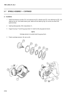
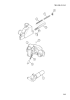
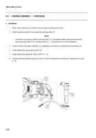
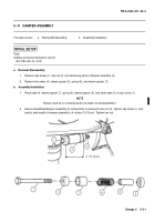
Place carrier assembly (4) in breech ring and aline operating crank holes.
2
Install operating handle (5) and operating crank assembly (3).
NOTE
The breech ring upper lug detent is stamped with a “U”; the adjuster detent (removed with adjuster
leaf spring pack (para 5--6)) is stamped with an “L”. These parts are not interchangeable.
3
Screw in breech ring upper lug detent (2), engaging annular groove of operating crank assembly (3).
4
Install adjuster leaf spring pack (para 5--6).
5
Install breechblock assembly (TM 9--2350--311--10).
6
Untie and release operating cam from cab roof. Perform adjustment procedures to operating cam (para
5--12).
3
5
2
4
Back to Top

