TM-9-2350-311-20-2 - Page 274 of 828
TM 9–2350–311–20–2
5–18
5–7
SPINDLE ASSEMBLY — CONTINUED
d.
Installation
1
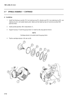
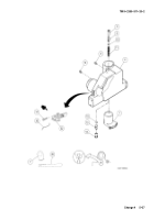
Install the following on spindle (19): front retaining ring (24), obturator pad (23), inner retaining ring (22), rear
retaining ring (21), and washer bearing (20). Make sure that retaining rings (21 and 24) are alined 180
°
apart as shown.
2
Install spindle assembly (18) in breechblock (1).
3
Support housing (17) and firing group block (4). Install nut (8) using spanner wrench.
NOTE
Cartridge extractor is located inside firing group block.
4
Position cartridge extractor (16) over nut (8).
18
1
19
24
23
22
21
20
8
17
4
16
Back to Top

