TM-9-2350-311-20-2 - Page 271 of 828
TM 9–2350–311–20–2
5–15
NOTE
•
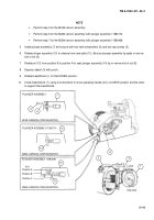
It is not necessary to remove the plunger assembly from the cannon assembly if only the spindle
assembly has to be removed for inspection or replacement.
•
Perform steps 4 and 5 for the M185 cannon assembly.
4
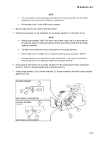
Move firing group block (4) to extreme right hand position.
5
Remove two cap screws (5), two lockwashers (6), and plunger assembly (7) until it clears nut (8).
NOTE
•
When plunger assembly 11580174 is lifted out and locked in place, the tip of the plunger will
provide some support in holding the housing and firing group block in place while the spindle
assembly is removed.
•
The M284 cannon assembly has two configurations for the plunger assembly.
•
Perform steps 6 and 7 for M284 cannon assembly containing plunger assembly 11580174.
•
If plunger assembly cannot be pulled out easily, a screwdriver or pry tool can be inserted be-
tween plunger tip and nut. Applying leverage will free plunger assembly.
6
Grasp spring pin (9) located on top of plunger assembly (10). Pull outward against helical compression
spring (11) until slot in plunger assembly lines up with cam plate (12).
7
Rotate plunger assembly (10) to lock with cam plate (12). Plunger assembly is now held in place and disen-
gaged from nut (8).
9
10
11
M284 CANNON CONFIGURATION
4
8
PLUNGER ASSEMBLY
11580174
12
7
PLUNGER ASSEMBLY
M185 CANNON CONFIGURATION
6
5
Back to Top

