TM-9-2350-311-20-2 - Page 277 of 828
TM 9--2350--311--20--2
Change 4
5--21
5--9
CARRIER ASSEMBLY
This task covers:
a.
Removal
b.
Disassembly
c.
Inspection
d.
Assembly
e.
Installation
INITIAL SETUP
Tools
Artillery and turret mechanic’s tool kit
(CL 5180--95--A12, see SC 9999--01--SKO)
Materials/Parts
GAA (item 18, Appx D)
Rope (item 26, Appx D)
Lockwire (V) (item 31, Appx G) M109A5**
Personnel Required
2
Equipment Condition
Breechblock assembly removed (TM 9--2350--311--10)
References
TM 9--2350--311--10
a. Removal
1
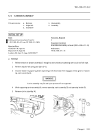
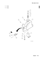
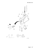
Relieve tension on damper assembly (1) enough to raise and secure operating cam to cab roof with rope.
2
Remove adjuster leaf spring pack (para 5--6).
3
Unscrew breech ring upper lug detent (operating crank detent) (2) which engages annular groove of operat-
ing crank assembly (3).
WARNING
Carrier assembly may fall and injure personnel if not supported.
4
While supporting carrier assembly (4), remove operating crank assembly (3) and operating handle (5).
5
Remove carrier assembly (4).
1
4
3
5
2
Back to Top

