TM-9-2350-311-20-2 - Page 272 of 828
TM 9–2350–311–20–2
5–16
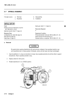
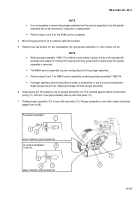
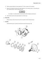
5–7
SPINDLE ASSEMBLY — CONTINUED
a.
Removal — Continued
NOTE
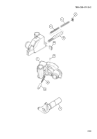
•
Perform step 8 for M284 cannon assembly containing plunger assembly 11580469.
•
When the plunger assembly is pulled out and locked in position B, the nut and spindle assembly
can be removed without the housing and firing group block.
•
the plunger assembly cannot be pulled out easily, a screwdriver or pry tool can be inserted be-
tween plunger tip and nut. Applying leverage will free plunger assembly.
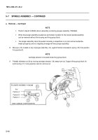
8
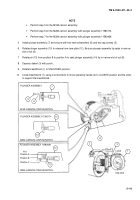
Move pin (13) located on top of plunger assembly (14), against helical compression spring (15) from position
A to position B.
NOTE
Cartridge extractor is located inside firing group block.
9
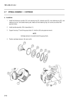
Partially withdraw nut (8) by moving cartridge extractor (16) away from nut. Support firing group block (4)
and housing (17). Using spanner wrench, remove nut.
8
17
4
16
Position A
Position B
Position C
“Pin”
PLUNGER ASSEMBLY 11580469
M284 CANNON CONFIGURATION
15
13
14
Back to Top

