TM-9-2350-311-20-2 - Page 287 of 828
TM 9–2350–311–20–2
Change 2
5–31
5–11 DAMPER ASSEMBLY
This task covers:
a.
Removal/Disassembly
b.
Assembly/Installation
INITIAL SETUP
Tools
Artillery and turret mechanic’s tool kit
(SC 5180–95–CL–A12)
a.
Removal/Disassembly
1
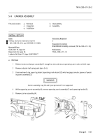
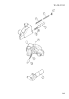
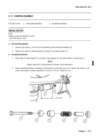
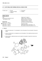
Remove cap screw (1), hex nut (2), and remaining parts of damper assembly (3).
2
Remove two seats (4), sleeve spacer (5), spring (6), and sleeve spacer (7).
b.
Assembly/Installation
1
Place seat (4), sleeve spacer (7), spring (6), sleeve spacer (5), and other seat (4) on cap screw (1).
NOTE
Breech must be in a closed position to obtain correct adjustment.
2
Secure assembled damper assembly (3) components in place with hex nut (2). Tighten cap screw (1) until
seat to seat length of damper assembly is 4 inches (10.16 cm). Tighten hex nut.
1
4
7
6
5
4
1
3
2
4” (10.16 cm)
Back to Top

