TM-9-2350-311-20-2 - Page 321 of 828
TM 9–2350–311–20–2
6–5
b.
Disassembly
1
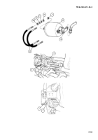
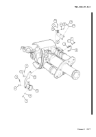
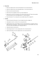
Remove four tapping screws (13) and mounting bracket (14) from instruction plate (15).
2
Remove four tapping screws (16) and sight gage bracket (17) from instruction plate (15).
3
Remove screw (18) and pointer handle (3).
4
Remove elbow (19) and adapters (20 and 21) from valve assembly (22).
5
Remove two hex nuts (23), two lockwashers (24), and two machine screws (25). Remove valve assembly
(22) and flat washer(s) (26) from sight gage bracket (17). Discard lockwashers.
6
Remove flat washer (27), clinch sleeve (28), and nonmetallic tubing (29) from adapter (21).
c.
Assembly
1
Install clinch sleeve (28), flat washer (27), and nonmetallic tubing (29) on adapter (21).
2
Install adapters (20 and 21) and elbow (19) on valve assembly (22).
3
Install flat washer(s) (26) on valve assembly (22). Add or subtract flat washer(s), as required, to aline non-
metallic tubing (29) on sight gage (1). Using two machine screws (25), two new lockwashers (24), and two
hex nuts (23), attach valve assembly (22) to sight gage bracket (17).
4
Install pointer handle (3) and screw (18).
5
Install sight gage bracket (17) and four tapping screws (16) on instruction plate (15).
6
Install mounting bracket (14) and four tapping screws (13) on instruction plate (15).
16
17
13
14
15
29
27
28
21
24
23
25
18
3
26
19
20
22
Back to Top

