TM-9-2350-311-20-2 - Page 322 of 828
TM 9–2350–311–20–2
6–6
6–1
GAGE ASSEMBLY, SIGHT — CONTINUED
d.
Installation
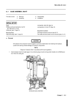
1
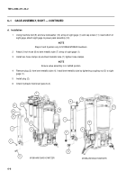
Using machine bolt (9) and new lockwasher (10) at top of sight gage (1) and cap screw (11) near bottom of
sight gage, attach sight gage to power pack assembly (12).
NOTE
Steps 2 and 3 pertain only to M109A4/M109A5 howitzers.
2
Attach 2-inch hose (8) to bent metallic tube (7) at top of sight gage (1).
3
Install two hose clamps (6) and bent metallic tube (7); tighten hose clamps.
NOTE
Ensure valve assembly is in GAGE postion.
4
Remove plug (2) from bent metallic tube (4). Install bent metallic tube by tightening coupling nut (5) to sight
gage (1).
5
Install plug (2).
6
Check hydraulic fluid level (para 6–2).
M109A2/M109A3 HOWITZER
M109A4/M109A5 HOWITZER
9
1
2
1
4
4
5
5
6
8
6
7
9
12
12
11
11
2
10
10
Back to Top

