TM-9-2350-311-20-2 - Page 450 of 828
TM 9–2350–311–20–2
8–26
8–4
CAB POWER LEAD ASSEMBLY — CONTINUED
a.
Removal — Continued
5
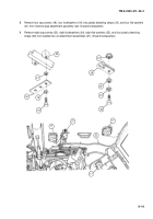
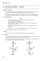
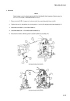
Remove three self-locking nuts (5), six flat washers (6), three plastic attaching straps (7), and three cap
screws (8) from cab power lead assembly positioned at turret lock. Discard self-locking nuts.
6
Remove 22 cap screws (9), 22 lockwashers (10), 22 flat washers (11), and 22 plastic attaching straps (12)
from cab power lead assembly at 22 hex nuts (13) welded to perimeter of cab ring. Discard lockwashers.
b.
Disassembly/Assembly
NOTE
•
Cab power lead assembly, wire 100, is taped into a wiring bundle with the following:
Power system wiring harness (intercom)
Gunner’s elevation control switch lead assembly
Panoramic telescope to dome light lead assembly (from cab traverse lock to below selector
valve assembly on cab race ring).
•
Tape must be removed from wiring bundle to remove any specific wiring harness. Apply tape
after assembly.
•
After assembly, check to ensure the wiring bundles will not be pinched by commander’s seat.
See repair procedures for harnesses, plugs, and terminals (para 8–1).
c.
Testing
Using multimeter, test cab power lead assembly for continuity through all plugs and connectors.
d.
Installation
1
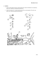
Install 22 plastic attaching straps (12), 22 flat washers (11), 22 new lockwashers (10), and 22 cap screws (9)
to cab power lead assembly on 22 hex nuts (13) welded to perimeter of cab ring.
2
Install three cap screws (8), three plastic attaching straps (7), six flat washers (6), and three new self-locking
nuts (5) to cab power lead assembly positioned at turret lock.
8
7
5
10
13
11
9
12
6
Back to Top


