TM-9-2350-311-20-2 - Page 456 of 828
TM 9–2350–311–20–2
8–32
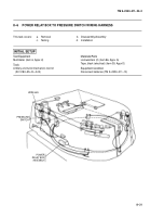
8–6
POWER RELAY BOX TO PRESSURE SWITCH WIRING HARNESS — CONTINUED
a.
Removal
NOTE
The power relay box to pressure switch wiring harness is taped into a wiring bundle and is removed
by removing the electrical tape. Replace tape as needed during installation.
1
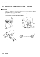
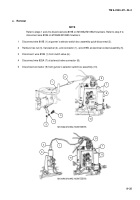
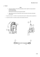
Disconnect female connector (1), wire 645, from power relay box assembly (2).
2
Disconnect connector (3), wire 645, from quick-disconnect near pressure switch (4).
3
Disconnect female connector (5) from pressure switch (4).
4
Remove two cap screws (6), two flat washers (7), two plastic attaching straps (8), and two lockwashers (9)
from power relay box to pressure switch wiring harness and vehicle. Discard lockwashers.
b.
Disassembly/Assembly
See repair procedures for harnesses, plugs and terminals (para 8–1).
c.
Testing
Using multimeter, test power relay box to pressure switch wiring harness for continuity through all plugs and
connectors.
d.
Installation
1
Install two plastic attaching straps (8), two flat washers (7), two new lockwashers (9), and two cap screws
(6) to power relay box to pressure switch wiring harness and to vehicle.
2
Connect female connector (5) to pressure switch (4).
3
Connect connector (3), wire 645, to quick-disconnect near pressure switch (4).
4
Connect female connector (1), wire 645, to power relay box assembly (2).
NOTE
After installation, check to ensure the wiring bundles will not be pinched by commander’s seat.
Back to Top

