TM-9-2350-311-20-2 - Page 465 of 828
TM 9–2350–311–20–2
Change 2
8–41
b.
Installation
1
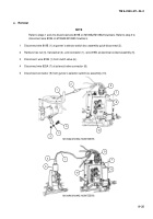
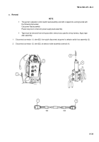
Install wire 623 in wiring bundle.
2
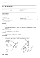
Install three plastic attaching straps (13), three new lockwashers (11), three cap screws (10), and three flat
washers (12) on three hex nuts (14) welded to cab.
3
Install three plastic attaching straps (9), three flat washers (8), three cap screws (7), three flat washers (6),
and three new self-locking nuts (5).
4
Connect connector (3), wire 623, at selector valve assembly solenoid (4).
5
Connect connector (1), wire 623, to quick-disconnect at gunner’s selector switch box assembly (2).
2
4
1
3
3
1
623
623
Back to Top

