TM-9-2350-311-20-2 - Page 460 of 828
TM 9–2350–311–20–2
8–36
8–7
CAB TRAVERSING MECHANISM HARNESS — CONTINUED
a.
Removal — Continued
6
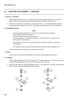
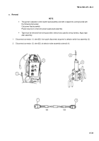
Remove wires 819B (1) and 825A (7) from sockets G (11) and C (12) of connector (9) (para 8–1).
b.
Disassembly/Assembly
See repair procedures for harnesses, plugs and terminals (para 8–1).
c.
Testing
Using multimeter, test cab traversing mechanism harness for continuity through all plugs and connectors.
d.
Installation
1
Install wires 819B (1) and 825A (7) in sockets G (11) and C (12) at connector (9). See information on how to
assemble connector (para 8–1).
2
Connect connector (9) to gunner’s selector switch box assembly (10).
3
Connect wire 825A (7) to solenoid valve connector (8).
NOTE
Refer to steps 4 and 5 to connect wire 819B on M109A2/M109A3 howitzers. Refer to step 6 to con-
nect wire 819B on M109A4/M109A5 howitzers.
4
Install hex nut (3), flat washer (4), and wire 819B (1) on electrical contact assembly (5).
5
Connect wire 819B (1) to quick-disconnect (2).
6
Install wire 819B (1) on top of clutch valve (6).
12
825A
625A
645
819B
100
GROUND
138
147
623
1
11
7
Back to Top

