TM-9-2350-311-20-2 - Page 477 of 828
TM 9–2350–311–20–2
8–53
a.
Removal
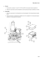
1
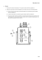
Disconnect J2 connector wiring harness (1) from gunner’s selector switch box assembly (2).
2
Remove four cap screws (3) and four flat washers (4) from the box mount (5) in the following manner:
(a)
Start by removing two cap screws (3) and two flat washers (4) on the left side of gunner’s selector
switch box assembly (2).
(b)
Loosen two cap screws (3) on right side of gunner’s selector switch box assembly (2).
(c)
Pull gunner’s selector switch box assembly (2) out toward the left and remove two cap screws (3) and
two flat washers (4) on the right side of gunner’s selector switch box assembly. Separate gunner’s se-
lector switch box assembly from box mount (5).
4
3
5
1
2
Back to Top


