TM-9-2350-311-20-2 - Page 478 of 828
TM 9–2350–311–20–2
8–54
8–12 GUNNER’S SELECTOR SWITCH BOX ASSEMBLY — CONTINUED
b.
Disassembly
NOTE
All wiring, desoldered or disconnected, must be tagged or marked to assure correct assembly.
3
Disconnect gunner’s selector switch box assembly (2) internal wiring before disassembling gunner’s selector
switch box assembly.
4
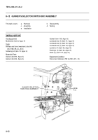
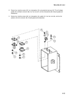
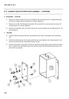
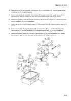
Remove lockwire (6), cap screw (7), and clamp (8) from gunner’s selector switch box assembly (2). Discard
lockwire.
5
Remove two hex nuts (9) and two seals (10) to remove two indicator lights (11). Remove two hex nuts (12).
Discard seals.
6
Remove three hex nuts (13), three washers (14), three key washers (15), and three switch guards (16) from
three toggle switches (17). Remove toggle switches and separate box (18) from gasket (19). Discard gasket.
7
Remove three hex nuts (20) and three packings (21) from three toggle switches (17). Discard packings.
13
14
15
16
18
19
21
20
17
10
9
8
6
7
12
11
2
Back to Top

