TM-9-2350-311-20-2 - Page 482 of 828
TM 9–2350–311–20–2
8–58
8–12 GUNNER’S SELECTOR SWITCH BOX ASSEMBLY — CONTINUED
c.
Assembly — Continued
20
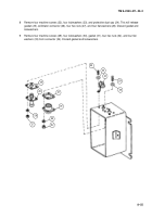
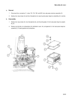
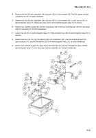
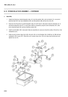
Install three new packings (21) and three hex nuts (20) on three toggle switches (17).
21
Aline holes of new gasket (19) and box (18). Insert three toggle switches (17) through three vertical holes in
gasket and box. Install three switch guards (16), three key washers (15), three washers (14), and three hex
nuts (13) on toggle switches (17).
22
Install two hex nuts (12) on two indicator lights (11).
23
Install two indicator lights (11) with two new seals (10) and two hex nuts (9).
24
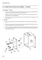
Install clamp (8), cap screw (7), and new lockwire (6) on gunner’s selector switch box assembly (2).
25
Connect internal wiring in gunner’s selector switch box assembly (2).
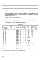
WIRING CHART
WIRE
FROM
TO
LUG TERMINAL
ITEM
SIZE
SPEC
LENGTH
UNIT
TERM. UNIT
TERM.
MS25036
NO.
AWG
–xxx
REQD
1
12
*
As reqd
J2
P
CB1
A
–156
1
2
12
*
As reqd
CB1
B
S1
3
–156,–111
1 EA
3
20
*
As reqd
S1
3
J1
A
–101
1
4
20
*
As reqd
CB1
B
DS1
3
–149
1
5
16
*
As reqd
S1
2
S2
2
–106
2
6
20
*
As reqd
S1
2
DS1
2
–101
1
7
16
*
As reqd
S2
1
J2
A
–106
1
8
20
*
As reqd
J2
N
CR1
ANODE
--
--
9
20
*
As reqd
J1
B
DS1
1
--
--
10
20
*
As reqd
DS1
1
DS2
1
--
--
11
20
*
As reqd
DS2
1
CR1
ANODE
--
--
12
16
*
As reqd
J2
F
CB1
B
–153
1
13
20
*
As reqd
DS1
3
DS2
3
--
--
14
16
*
As reqd
S3
3
J2
C
–106
1
15
16
*
As reqd
S3
6
J2
6
–106
1
16
20
*
As reqd
S3
6
CR1 CATHODE
–101
1
17
20
*
As reqd
S3
6
DS2
2
–101
1
18
16
*
As reqd
S2
2
S3
2
–106
2
19
16
*
As reqd
S2
2
S3
5
–106
2
20
16
*
As reqd
S3
5
J2
E
–106
1
*NOTE: HW–C–12–(19)–U–9, MW–C–16–(19)–U–9, and MW–C–20–(7)–U–9.
Back to Top


