TM-9-2350-311-20-2 - Page 490 of 828
TM 9–2350–311–20–2
8–66
8–13 POWER RELAY BOX ASSEMBLY — CONTINUED
c.
Assembly — Continued
1
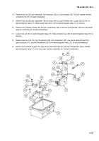
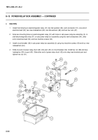
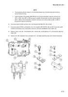
Install distribution cover (10) and new gasket (11) on cab power relay box assembly (2) using six bolts (8)
and six new lockwashers (9).
2
Install mounting plate (7) on cab power relay box assembly (2) using eight cap screws (5) and eight flat
washers (6).
d.
Installation
1
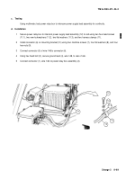
Install four cap screws (3) to secure cab power relay box assembly (2) to mount (4).
2
Connect four connectors (1), wires 100, 104, 148, and 645, at cab power relay box assembly (2).
8
9
10
11
6
5
7
1
3
4
2
1
Back to Top

