TM-9-2350-311-20-2 - Page 492 of 828
TM 9–2350–311–20–2
8–68
Change 2
8–14 POWER RELAY BOX TO INTERCOM POWER SUPPLY LEAD ASSEMBLY
— CONTINUED
a.
Removal
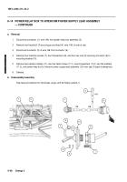
1
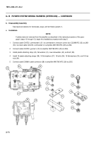
Disconnect connector (1), wire 148, from power relay box assembly (2).
2
Remove hex head bolt (3) securing ground lead (4), wire 148, to rear of cab.
3
Disconnect connector (5) of wire 148 from connector (6).
4
Remove four machine screws (7), four flat washers (8), and four hex nuts (9) securing connector (6) to
mounting bracket (10).
5
Remove two harness clamps (11), two hex head screws (11.1), two lockwashers (11.2), two flat washers
(11.3), and power relay box to intercom power supply lead assembly (12) from cab. Discard lockwashers.
6
Deleted.
b.
Disassembly/Assembly
See repair procedures for harnesses, plugs, and terminals (para 8–1).
1
6
4
148
148
5
6
3
4
9
8
7
148
1
2
10
Back to Top

