TM-9-2350-311-20-2 - Page 500 of 828
TM 9–2350–311–20–2
8–76
Change 2
8–15 POWER SYSTEM WIRING HARNESS (INTERCOM) — CONTINUED
c.
Installation — Continued
10
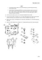
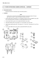
Install connector wiring harness (8) on mounting bracket (9).
11
Install telephone ground wire (12), ground lead (11), and cap screw (10) to cab.
12
Install connector (4) on mounting bracket (9). Install four machine screws (5), four flat washers (6), and four
hex nuts (7) on mounting bracket (9).
13
Tape connector wiring harness as required. Tape wiring bundles as necessary.
NOTE
After assembly, check to ensure wiring bundles will not be pinched by the commander’s seat.
14
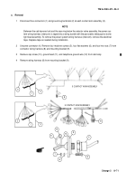
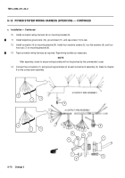
Connect five connectors (1) and ground lug terminals (2) at each contact arm assembly (3). Refer to chapter
9 on the contact arm assembly.
8
2
5 CONTACT ARM ASSEMBLY
3 CONTACT ARM ASSEMBLY
2
3
3
1
1
8
10
12
11
7
5
6
4
9
Back to Top


