TM-9-2350-311-20-2 - Page 505 of 828
TM 9–2350–311–20–2
9–3
a.
Removal
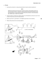
WARNING
While performing all procedures in this section except for testing, disconnect the battery ground ca-
ble at battery terminal to cut off cab electrical power. Failure to observe this warning could result in
severe burns and electrical shock, resulting in injury or death.
NOTE
This procedure is written for one contact arm assembly, but applies to all five.
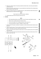
1
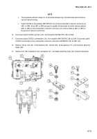
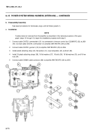
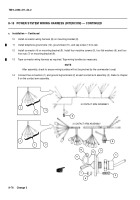
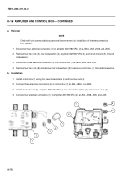
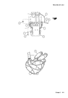
Remove hex nut (1), lockwasher (2), machine bolt (3), and power cable (4) at bus bar terminal (5). Discard
lockwasher.
NOTE
All harnesses must be tagged or marked to assure correct assembly.
2
Remove five machine screws (6) and five lockwashers (7) securing harness (8) and telephone intercom har-
ness (9). Lift off harnesses. Discard lockwashers.
CAUTION
Use care in removing or installing ring segment. Place ring segment in a safe place to prevent dam-
age to the silver contact surface.
3
Remove ten self-locking screws (10) and ten flat washers (11) to release ring segment (12). Discard self-
locking screws.
10
11
12
5
3
1
2
6
7
4
8
9
Back to Top

