TM-9-2350-311-20-2 - Page 513 of 828
TM 9–2350–311–20–2
Change 2
9–11
6
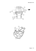
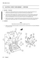
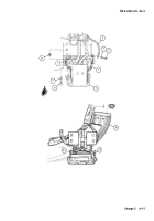
Remove four machine screws (27) securing two electrical contact brushes (12) and two ground electrical
contact brushes (18).
7
Remove two electrical contact brushes (12), two ground electrical contact brushes (18), and eight springs
(28) from electrical contact holder (29).
8
Remove six machine screws (30), four machine screws (31), and five electrical contact brushes (32) with
attached leads (33) from electrical contact holder (29).
NOTE
Perform step 9 only if wires are broken or defective.
9
Unsolder electrical lead (33) from electrical contact brush (32).
c.
Assembly
NOTE
•
When reassembling electrical contact brushes (12 and 18), adjust to same height as contacts.
•
Apply one drop of sealing compound to thread of screws.
•
Use rosin core solder only. For soldering instructions, refer to para 2–16.
•
Use wiring schematic as a guide for installation of electrical leads.
1
If electrical lead (33) has been unsoldered for replacement, solder new electrical lead to electrical contact
brush (32).
2
Install four machine screws (31) and six machine screws (30) on five electrical brushes (32) with attached
leads (33), alining wires in grooves to electrical contact holder (29).
3
Install four springs (28) and two electrical contact brushes (12) with two machine screws (27) into electrical
contact holder (29).
4
Install four springs (28) and two ground electrical contact brushes (18) with two machine screws (27) into
electrical contact holder (29).
18
12
33
30
27
28
28
32
29
100
GND
100
GND
41
42
43
L1
L2
31
Back to Top


