TM-9-2350-311-20-2 - Page 514 of 828
TM 9–2350–311–20–2
9–12
Change 2
9–3
ELECTRICAL CONTACT ARM ASSEMBLY — CONTINUED
c.
Assembly
— Continued
5
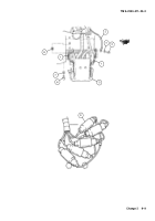
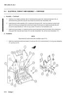
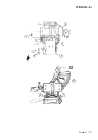
Install two non-metallic grommets (26) on mechanical drive guard (22). Install terminal board (14) on
mechanical drive guard (22) using two cap screws (24) and two new lockwashers (25).
6
Install electrical holder assembly (23) in mechanical drive guard (22). Insert two electrical contact brush
leads (12) and two ground electrical contact brush leads (18) through non-metallic grommets (26) and
secure two angle brackets (21) with four cap screws (19) and four new lockwashers (20).
7
Attach two ground straps (1) (if present) and two ground electrical contact brush leads (18) to mechanical
drive guard (22) using two cap screws (15), two new lockwashers (16), and two new lockwashers (17).
d.
Installation
NOTE
Adjust electrical contact arms after installation (para 9–3f.).
1
Attach two electrical contact brush leads (12) and wire 100 (13) to terminal board (14) using new lockwasher
(11) and hex nut (10).
26
25
24
25
24
22
26
14
21
19
20
15
16
17
18
12
11
10
23
14
13
1
5
22
1
12
18
Back to Top

