TM-9-2350-311-20-2 - Page 518 of 828
TM 9–2350–311–20–2
9–16
Change 2
9–3
ELECTRICAL CONTACT ARM ASSEMBLY — CONTINUED
f.
Adjustment
1
Ensure MASTER switch (36) is OFF.
2
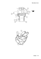
Manually traverse cab until electrical contact arm (5) is under ring segment (35).
3
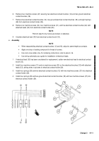
Set the feeler gage to measure a thickness of 0.105 inch (2.67 mm). Place feeler gage between rails of ring
segment (35) and surface of electrical holder assembly (23) closest to mounting bracket. Make sure that
clearance between the surface of the electrical holder assembly and the surface of the ring segment is
0.105
±
0.002 inch (2.67
±
0.05 mm). To adjust the clearance between the two surfaces, vertically lift the
electrical contact arm (5). Measurement must be taken on both sides of the rear surface of the electrical
holder assembly.
4
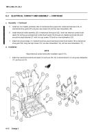
Measure for proper clearance on the forward side of the electrical holder assembly (23). If forward side of
electrical holder assembly is less than 0.105
±
0.002 inch (2.67
±
0.05 mm), add shims (8) to bottom mount-
ing cap screws (6). If forward side is greater than 0.105
±
0.002 inch (2.67
±
0.05 mm), add shims (8) to top
mounting cap screws (6). When proper clearance is achieved, tighten the four cap screws.
5
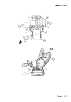
Ensure horizontal alinement of electrical contact arm (5) and rails of ring segment (35) by loosening cap
screws (19) on angle bracket (21) and sliding assembly forward or backward to obtain and maintain aline-
ment throughout procedure.
6
Once correct clearance and alinement is obtained, torque all cap screws to specifications listed in Table
F–1. Reverify all clearances and alinements.
7
Repeat this procedure for remaining electrical contact arms.
NOTE
•
Illustrations show slip ring covers removed for clarity.
•
The electrical contact brushes of electrical contact arms can be adjusted quickly and easily by
using locally made adjustment gages. Gages can be made from fiberboard. Gage material
should be 0.105
±
0.002 inch (2.67
±
0.05 mm) thick. Closest fractional dimension for thickness
is 7/64 inch (2.78 mm).
Back to Top


