TM-9-2350-311-20-2 - Page 510 of 828
TM 9–2350–311–20–2
9–8
Change 2
9–3
ELECTRICAL CONTACT ARM ASSEMBLY
This task covers:
a.
Removal
b.
Disassembly
c.
Assembly
d.
Installation
e.
Cleaning
f.
Adjustment
INITIAL SETUP
Tools
Artillery and turret mechanic’s tool kit
(SC 5180–95–CL–A12)
Contact brush adjustment gage (Figure E–1, Appx E)
Soldering torch kit (item 13, Appx H)
Soldering gun (item 12, Appx H)
Materials/Parts
Cleaning compound (item 9.1, Appx D)
Flux (item 15, Appx D)
Lockwashers (5) (item 55, Appx G)
Lockwashers (4) (item 56, Appx G)
Lockwashers (6) (item 64, Appx G)
Lockwashers (2) (item 79, Appx G)
Rosin core solder (item 34, Appx D)
Sealing compound (item 30, Appx D)
Shims (V) (item 111, Appx G)
Equipment Condition
Disconnect batteries (TM 9–2350–311–20–1)
a.
Removal
WARNING
While performing all procedures in this section except for adjustment, disconnect the battery ground
cable at battery terminal to cut off cab electrical power. Failure to observe this warning could result in
severe burns and electrical shock, resulting in injury or death.
NOTE
Perform these procedures for each of 3 or 5 electrical contact arm assemblies.
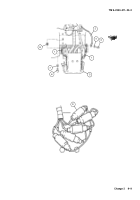
1
Disconnect ground straps (1) and ground wire (2) by removing one cap screw (3) and lockwasher (4) from
each side of the electrical contact arm (5). Discard lockwasher.
2
Remove electrical contact arm (5) by removing four cap screws (6), four lockwashers (7), and shims (8).
Discard lockwashers and shims.
3
Disconnect five electrical leads at quick disconnects (9).
Back to Top

