TM-9-2350-311-20-2 - Page 512 of 828
TM 9–2350–311–20–2
9–10
Change 2
9–3
ELECTRICAL CONTACT ARM ASSEMBLY — CONTINUED
a.
Removal — Continued
4
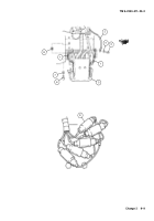
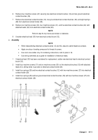
Remove hex nut (10) and lockwasher (11) securing two electrical contact brush leads (12) and wire 100 (13)
to terminal board (14). Discard lockwasher.
b.
Disassembly
NOTE
Ground straps may not be on all electrical contact arms.
1
Remove two cap screws (15), two lockwashers (16), and two lockwashers (17) from electrical contact arm
(5) to remove both ground straps (1) and two ground electrical contact brush leads (18). Discard lockwash-
ers.
2
Remove four cap screws (19) and four lockwashers (20) and two angle brackets (21) from mechanical drive
guard (22). Discard lockwashers.
3
Remove electrical
holder assembly (23) from mechanical drive guard (22).
4
Remove two cap screws (24) and two lockwashers (25) securing terminal board (14) to mechanical drive
guard (22). Discard lockwashers.
5
Remove two non-metallic grommets (26) from mechanical drive guard (22).
21
19
20
15
16
17
18
12
11
10
23
14
13
1
5
22
1
12
18
26
25
24
25
24
22
26
14
Back to Top

