TM-9-2350-311-20-2 - Page 502 of 828
TM 9–2350–311–20–2
8–78
8–16 AMPLIFIER AND CONTROL BOX — CONTINUED
a.
Removal
NOTE
Check with unit communications personnel before removal or installation of the intercommunica-
tions system.
1
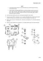
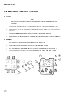
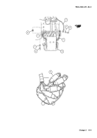
Disconnect four electrical connectors (1) on amplifier AM1780/VRC (2) at J504, J508, J506, and J505.
2
Remove four hex nuts (3), four lockwashers (4), amplifier AM1780/VRC (2), and shock mounts (5). Discard
lockwashers.
3
Disconnect three electrical connectors (6) from control box (7) at J804, J802, and J803.
4
Remove four hex nuts (8) and remove four lockwashers (9) to remove control box (7). Discard lockwashers.
b.
Installation
1
Install control box (7) using four new lockwashers (9) and four hex nuts (8).
2
Connect three electrical connectors (6) to control box (7) at J804, J802, and J803.
3
Install shock mounts (5), amplifier AM1780/VRC (2), four new lockwashers (4) and four hex nuts (3).
4
Connect four electrical connectors (1) to amplifier AM1780/VRC (2) at J504, J508, J506, and J505.
3
4
5
2
1
8
9
6
7
Back to Top

