TM-9-2350-311-20-2 - Page 495 of 828
TM 9–2350–311–20–2
Change 2
8–71
a.
Removal
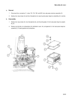
1
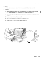
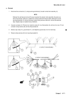
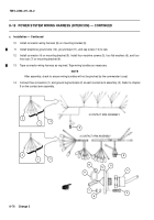
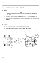
Disconnect five connectors (1) and ground lug terminals (2) at each contact arm assembly (3).
NOTE
Between the cab traverse lock and the race ring below the selector valve assembly, the power sys-
tem wiring harness (intercom) is taped into a wiring bundle with the panoramic telescope to dome
light lead assembly. To remove the power system wiring harness (intercom), remove the electrical
tape. Replace tape as needed during installation.
2
Unscrew connector (4). Remove four machine screws (5), four flat washers (6), and four hex nuts (7) from
connector wiring harness (8) and mounting bracket (9).
3
Remove cap screw (10), ground lead (11), and telephone ground wire (12) from cab body.
4
Remove wiring harness (8) from mounting bracket (9).
8
2
5 CONTACT ARM ASSEMBLY
3 CONTACT ARM ASSEMBLY
2
3
3
1
1
8
10
12
11
7
5
6
4
9
Back to Top

