TM-9-2350-311-20-2 - Page 498 of 828
TM 9–2350–311–20–2
8–74
8–15 POWER SYSTEM WIRING HARNESS (INTERCOM) — CONTINUED
b.
Disassembly/Assembly
See repair procedures for harnesses, plugs, and terminals (para 8–1).
c.
Installation
NOTE
If cables were not removed from the amplifier as described in the removal procedure of this para-
graph (steps 10 through 13), begin this installation procedure with step 5.
1
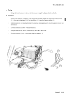
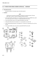
Connect cable CX4723, commander’s (31) to commander’s intercom control box C2298/VRC (32) at J801
(33). Connect cable CX4723, commander’s to amplifier AM1780/VRC (29) at J504.
2
Connect cable CX4723, gunner’s (30) to amplifier AM1780/VRC (29) at J506.
3
Install plastic attaching strap (42), flat washer (41), new lockwasher (40), and bolt (39).
4
Install 16 plastic attaching straps (38), 16 flat washers (37), 16 bolts (36), 16 flat washers (35), and 16 hex
nuts (34).
5
Connect cable CX9640 cable connector (28) to amplifier AM1780/VRC (29) at J505.
36
37
38
35
34
39
40
41
29
30
31
32
33
42
28
J801
Back to Top

