TM-9-2350-311-20-2 - Page 496 of 828
TM 9–2350–311–20–2
8–72
Change 2
8–15 POWER SYSTEM WIRING HARNESS (INTERCOM) — CONTINUED
a.
Removal — Continued
5
Deleted
6
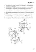
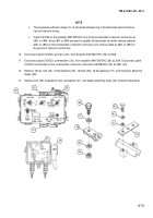
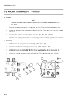
Remove telephone wire leads L1 and L2 (13) from telephone wire lead terminals (14).
7
From the 20 welded on hex nuts (15), remove 20 flat washers (16), 20 cap screws (17), 20 flat washers
(18), and 20 plastic attaching straps (19). Remove three hex nuts (20), three flat washers (21), three cap
screws (22), three flat washers (23), three plastic attaching straps (24), and wiring harness (25).
8
Remove bolt (26), lockwasher (26.1), flat washer (26.2), and plastic attaching strap (27). Discard
lockwasher.
9
Disconnect cable CX9640 cable connector (28) from amplifier AM1780/VRC (29) at J505.
22
23
24
21
20
17
18
19
16
15
J505
13
13
14
29
25
26
28
27
J506
26.1
26.2
Back to Top


