TM-9-2350-311-20-2 - Page 497 of 828
TM 9–2350–311–20–2
8–73
NOTE
•
The procedure outlined in steps 10–13 should be followed only if the technician wants to discon-
nect all intercom wiring.
•
Cable CX4723 on the amplifier AM1780/VRC runs to the commander’s intercom control box at
J801 or J804. Since J801 or J804 are wired in parallel, the technician can either remove cable at
J801 or J804 on the commander’s intercom control box and remove cable at J801 or J804 on
the gunner’s intercom control box.
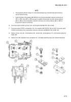
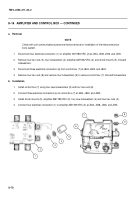
10
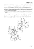
Disconnect cable CX4723, gunner’s (30), from amplifier AM1780/VRC (29) at J506.
11
Disconnect cable CX4723, commander’s (31) from amplifier AM1780/VRC (29) at J504. Disconnect cable
CX4723 commander’s from commander’s intercom control box C2298/VRC (32) at J801 (33).
12
Remove 16 hex nuts (34), 16 flat washers (35), 16 bolts (36), 16 flat washers (37), and 16 plastic attaching
straps (38).
13
Remove bolt (39), lockwasher (40), flat washer (41), and plastic attaching strap (42). Discard lockwasher.
36
37
38
35
34
39
40
41
29
30
31
32
33
42
28
J801
Back to Top

