TM-9-2350-311-20-2 - Page 489 of 828
TM 9–2350–311–20–2
8–65
5
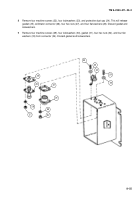
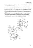
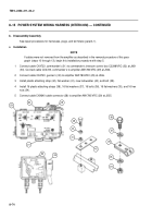
Using hex nut (33) and new lockwasher (34), install terminal connecting link (37) on post (35) of circuit
breaker (36).
6
Slide conductor bus (46) onto electromagnetic relay (31) and tighten hex nut (45) on relay load terminal
post.
7
Position new gasket (32) over screw holes and insert connector (23) with attached electrical lead (30) into
cab power relay box assembly (1). Install four machine screws (20) and four new lockwashers (21) on con-
nector (23). Using hex nut (28) and new lockwasher (29), install electrical lead (30) on electromagnetic relay
(31).
8
Position new gasket (27) over screw holes and insert connector (22) into cab power relay box assembly (2),
and secure with four new lockwashers (21) and four machine screws (20). Aline connector (22) with prongs
of terminal connecting link (37) and conductor bus (46). Install flat washer (26), new lockwasher (25), and
hex nut (24).
9
Install new gasket (19), connector (14), four new lockwashers (13), and four machine screws (12). Aline
connector (14) with prong of terminal connecting link (37) inside cab power relay box assembly (2). Connect
connector (14) to terminal connecting link (37) using two flat washers (18), new lockwasher (17), and hex
nut (16).
10
Install new gasket (19), connector (14), four new lockwashers (13), and four machine screws (12). Aline
connector (15) with prong of conductor bus (46) inside cab power relay box assembly (2). Connect connec-
tor (15) to conductor bus (46) using two flat washers (18), new lockwasher (17), and hex nut (16).
30
28
31
26
25
24
19
16
17
18
15
13
12
23
30
32
27
21
22
20
19
16
17
18
14
13
12
29
2
Back to Top

