TM-9-2350-311-20-2 - Page 480 of 828
TM 9–2350–311–20–2
8–56
8–12 GUNNER’S SELECTOR SWITCH BOX ASSEMBLY — CONTINUED
b.
Disassembly — Continued
10
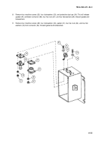
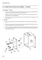
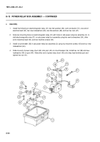
Remove four machine screws (35) and four lockwashers (36) from blank panel (37). Separate blank panel
from gunner’s selector switch box assembly (2). Discard lockwashers.
11
Remove hex nut (38). This will release lockwasher (39), lug terminal (40), and semi-conductor device (41)
from blank panel (37). Discard lockwasher.
12
Remove two lockwashers (42), two machine screws (43), and circuit breaker (44) from blank panel (37). Dis-
card lockwashers.
c.
Assembly
13
Using two machine screws (43) and two new lockwashers (42), attach circuit breaker (44) to blank panel
(37).
14
Insert semi-conductor device (41) through lug terminal (40), new lockwasher (39), and blank panel (37). At-
tach semi-conductor device to blank panel using hex nut (38).
15
Aline four screw holes on blank panel (37) with four screw holes inside gunner’s selector switch box assem-
bly (2). Using four new lockwashers (36) and four machine screws (35), attach blank panel to gunner’s se-
lector switch box assembly.
41
40
39
43
37
36
35
44
42
2
38
Back to Top

